02.120.0501: Jamb Detail – Storm Shelter Window / Door Jamb
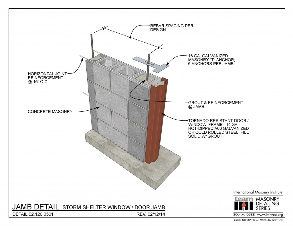 02.120.0501: Jamb Detail - Storm Shelter Window / Door Jamb DOWNLOAD DETAIL
 02.120.0102: Wall Section – Hybrid Wall System
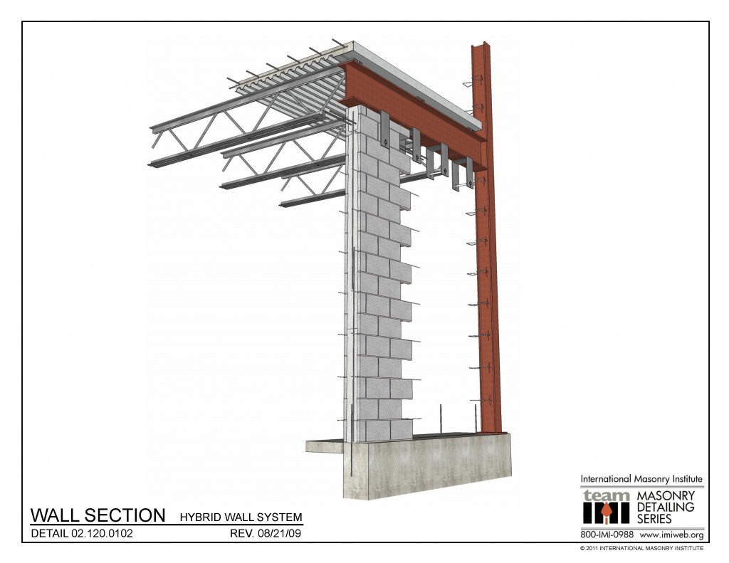 02.120.0102: Wall Section - Hybrid Wall System DOWNLOAD DETAIL
 02.120.0101: Wall Section – Hybrid Wall System
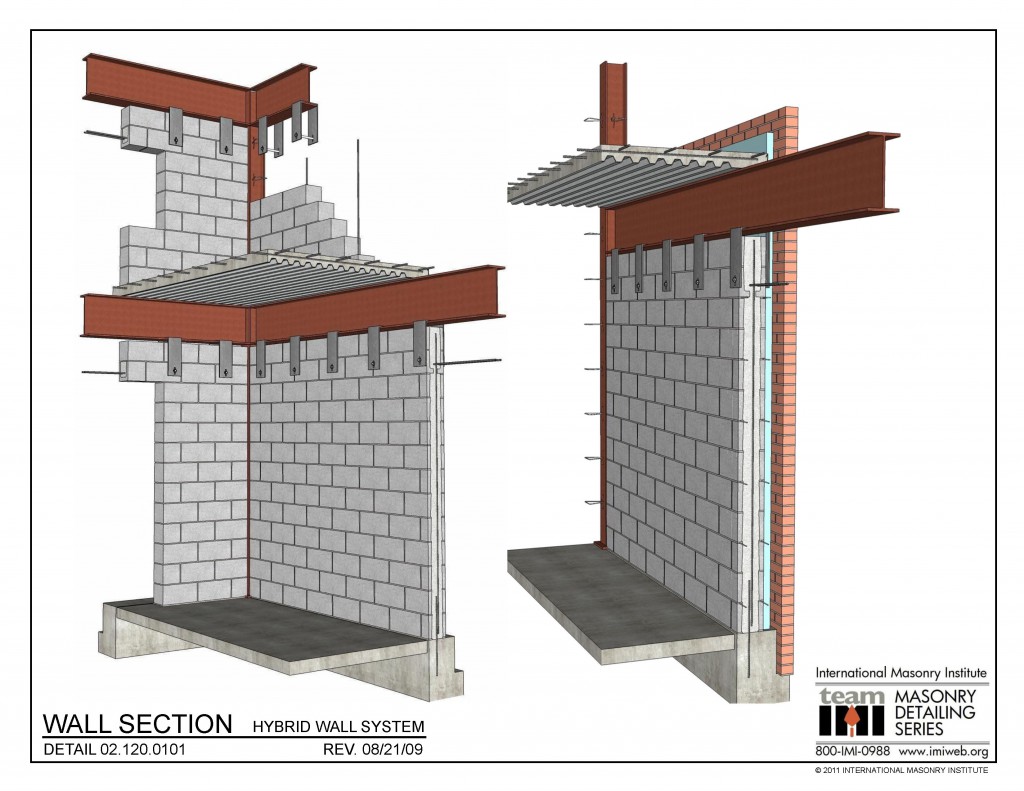 02.120.0101: Wall Section - Hybrid Wall System DOWNLOAD DETAIL
 02.020.0202: Vertical Span – CMU Partition
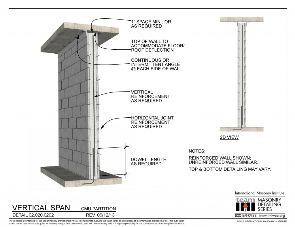
This partition detail shows a vertical span condition. The wall is anchored at the base with a vertical dowel into the slab. There is a gap at the top of the wall to allow for deflection of the structure above. Horizontal joint reinforcement and vertical reinforcement are shown. Top and bottom detailing may vary.
02.010.0801: Masonry Wall Cap – Single Wythe CMU
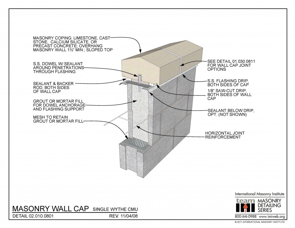 02.010.0801: Masonry Wall Cap - Single Wythe CMU This detail shows a concrete masonry (CMU) wall, top of wall detail. The wall cap is anchored to the grouted wall with a vertical dowel through the flashing, which is then sealed around the dowel penetration. The flashing is shown as a flexible material for the through-wall [...]
 02.010.0702: Concrete Masonry Firewall – T/ Wall at Slab Above
 02.010.0702: Concrete Masonry Firewall - T/ Wall at Slab Above DOWNLOAD DETAIL
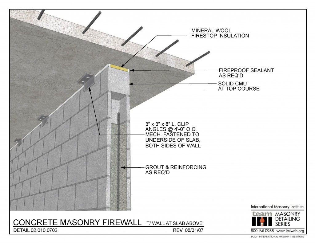
 02.010.0313: Base of Wall – Single Wythe Block, Proprietary Flashing/Weeps
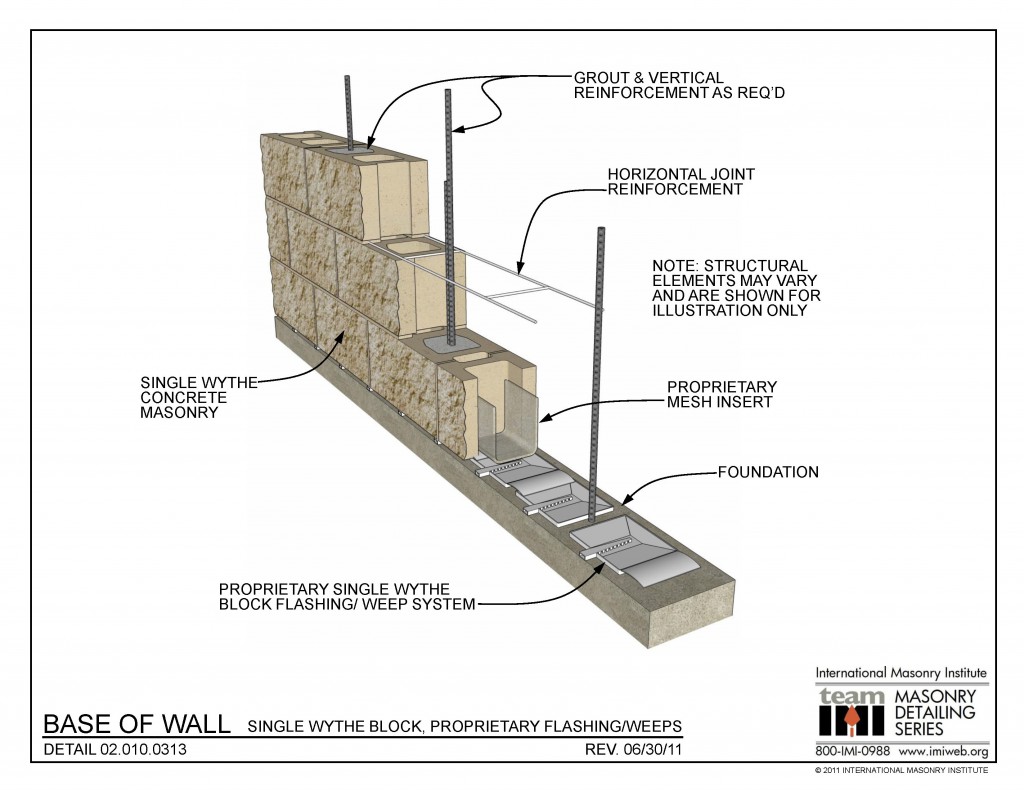 02.010.0313: Base of Wall - Single Wythe Block, Proprietary Flashing/Weeps This detail shows an 8” (nominal) split face concrete masonry (CMU) wall, base of wall condition. A proprietary system of flashing and weeps resides at the bottom of the cells, with mesh inserts to keep mortar from interfering with water exiting the wall through the [...]
 02.010.0301: Foundation Dowel Alignment
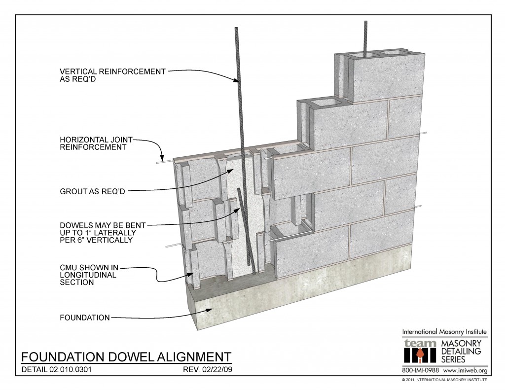 02.010.0301: Foundation Dowel Alignment This detail shows a concrete masonry (CMU) wall in partial longitudinal section. In case the foundation dowels do not coincide with the center of the CMU cells, dowels may be bent 1” laterally for every 6” vertically. Vertical reinforcement overlaps the dowels to achieve sufficient development strength per structural design. DOWNLOAD [...]
 02.120.1501: Wall Intersection Detail
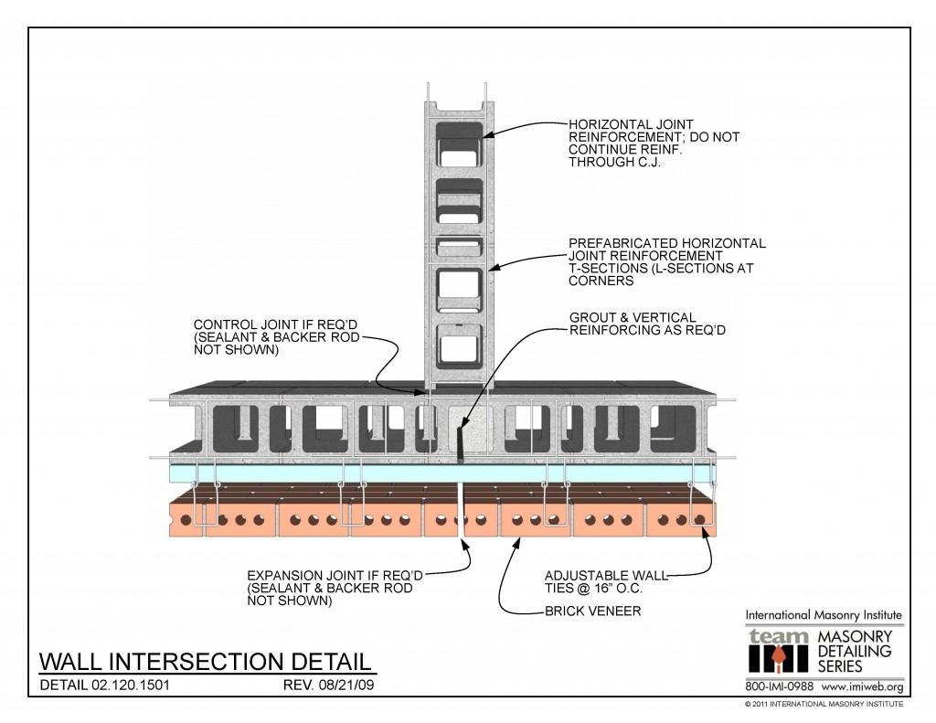 02.120.1501: Wall Intersection Detail DOWNLOAD DETAIL
 02.120.1102: Column Connection Details – Option 2
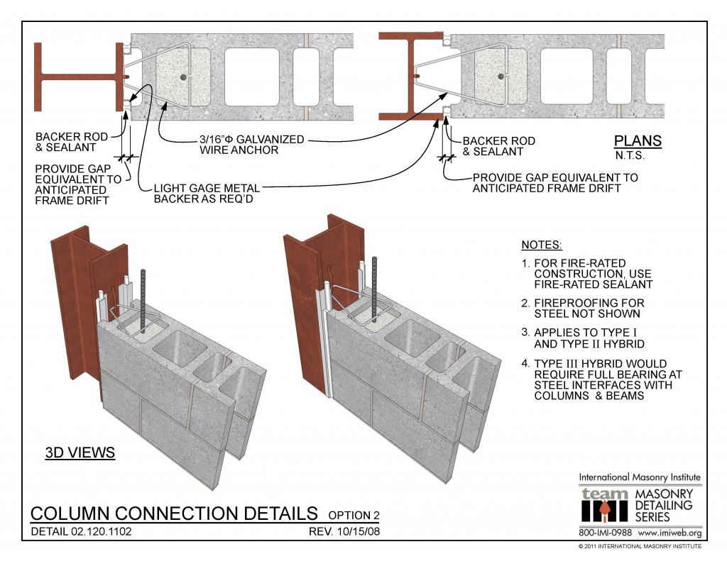
This detail shows the connection of a loadbearing CMU wall to a steel column as part of a hybrid masonry and steel structural system. The CMU is anchored to the column with a 3/16″ dia. galvanized wire anchor held to the column with a welded bar. Fireproofing on the steel is not shown for clarity. […]